Flange Measurement Best Practices
Flange measurement is the systematic process of recording pipe flange dimensions and related bolting parameters to ensure a leak-free, mechanically sound joint in piping systems. Accurate flange measurement directly influences sealing integrity, pressure containment, and procurement accuracy, and material-specific factors such as aluminum flange thermal expansion must be considered during measurement and installation. This guide explains which dimensions matter, how to read ASME B16.5 and related charts, material-specific best practices for aluminum, steel, stainless, and alloy flange types, and how to apply proper flange bolt torque specifications to achieve leak-proof connections. Readers will find procedural checklists, torque reference tables, and practical troubleshooting steps for common measurement errors. Sections cover key dimensions to measure, standard interpretation, aluminum-specific guidance including alloy effects, bolting and gasket selection, quality-control strategies tied to industry standards, and recommended measurement tools and calculators to optimize accuracy.
What Are the Key Pipe Flange Dimensions to Measure for Accurate Fit?
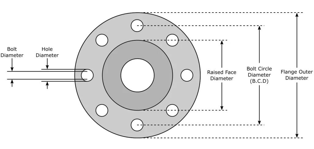
Measuring the correct pipe flange dimensions begins with identifying the critical geometry that determines fit and sealing performance: outer diameter (OD), inner diameter (ID), flange thickness, raised or groove face inner/outer diameter (critical for optimal gasket sealing), bolt circle diameter (BCD), bolt hole diameter, and number of bolt holes. These dimensions collectively determine gasket seating area, bolt length and pattern, and mating compatibility with standard flange charts such as ASME B16.1 industry standard, B16.47 large diameter, B16.36 orifice instrumentation, and modern B16.5. Accurate measurement reduces rework, ensures correct gasket selection, and streamlines procurement by matching measured values to standard flange sizes. The next subsections walk through step-by-step methods for each critical dimension and explain why each measurement matters for flange face type and tolerances.
How Do You Measure Outer Diameter and Inner Diameter of Flanges?
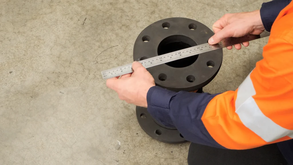
Outer diameter (OD) and inner diameter (ID) establish flange mating and pipe bore continuity, and both require consistent reference points to avoid measurement error. Use a recently calibrated digital caliper for smaller flanges and an accurate steel tape or flange ruler for larger diameters; zero the instrument and take readings at multiple, evenly spaced points to average out eccentricity and ovality. Measure the OD at the widest radial point and the ID at the bore edge, avoiding chamfers and threads that can skew the reading; record units (in/mm) and allowed tolerances as defined in ASME B16.5 section 7.1 through 7.8 and available on our Texas Flange catalog page 13. Additional informational data regarding metric and imperial conversion tolerances described in our section. This consistent measurement technique ensures that OD/ID values map correctly to standard flange dimensions and lowers the risk of mismatch when selecting replacement flanges or gaskets.
What Is the Importance of Flange Thickness and How Is It Measured?
Flange thickness contributes to structural integrity and pressure rating and is distinct from raised face height or ring-type joint depths; thickness directly affects bending resistance under bolt preload and internal pressure. Measure thickness with a digital thickness gauge or caliper across several radial points to find minimum, maximum, and average values; note that machining tolerances and corrosion can change thickness locally and should be documented. Accurate thickness measurement informs pressure-class verification against standards and influences bolt length selection to ensure adequate engagement without over-compression of the gasket. Recording thickness alongside face condition lets inspectors determine whether repair, machining, or replacement is needed to meet design and safety criteria.
How to Determine Bolt Circle Diameter and Bolt Hole Size Accurately?
Bolt circle diameter (BCD) and bolt hole diameter determine bolt positioning, distribution of clamping load, and compatibility with mating flanges or flanged equipment. Measure BCD by finding center-to-center coordinates of opposite bolt holes or by measuring the distance between two non-adjacent holes and using simple geometry for odd patterns; use a center-finding template or large calipers for accuracy on bigger flanges. Measure bolt hole diameter at the narrowest section and inspect countersink or chamfer dimensions that affect bolt fit and sleeve or gasket seating. Accurate BCD and hole-size records ensure correct bolt selection, avoid misalignment during assembly, and simplify cross-checking with standard dimension tables.
How Do Flange Face Types Affect Measurement Techniques?
Flange face types—Raised Face (RF), Flat Face (FF), and Ring-Type Joint (RTJ)—change where and how you measure critical dimensions and which gasket types are appropriate for sealing. Raised Face requires measuring raised face height in addition to thickness, as the raised area concentrates gasket compression; Flat Face needs precise face flatness checks across the entire sealing surface. RTJ flanges require measurement of ring groove dimensions and groove geometry to ensure proper metal-to-metal sealing with corresponding ring joints. Understanding face type guides both measurement points and acceptable tolerances, and it directs correct gasket and bolting strategies to achieve a reliable seal.
How to Read and Use Pipe Flange Dimensions Charts Including ASME B16.5 Standards?
Reading flange dimension charts like ASME B16.5 means mapping nominal pipe size and pressure class to specific geometric values such as OD, BCD, flange thickness, and bolt hole count and size. Charts are organized by nominal pipe size (NPS) and pressure class (150, 300, 600, etc.), with each row listing the standard dimensions that mating flanges must meet for interchangeability. To use a chart, identify measured NPS/OD, locate the appropriate pressure class, and verify BCD and bolt hole diameter against the table values; always confirm units and whether the chart uses ASME or alternative standard numbering.
What Are the ASME B16.5 Flange Dimensions and Pressure Classes?
ASME B16.5 defines flange dimensions for pipe sizes up to NPS 24 and organizes dimensions by pressure classes such as 150, 300, and 600, each of which prescribes different wall profiles, bolt patterns, and thicknesses to meet pressure and temperature capabilities. Pressure class affects flange thickness and bolt circle diameter because higher pressure classes demand greater structural capacity and larger bolt patterns for load distribution. When interpreting a B16.5 table, compare measured thickness and BCD against the class row and verify gasket and bolt specifications accordingly. Using B16.5 as the baseline simplifies procurement and verification, but always check manufacturer tolerances and material-specific notes for aluminium flanges where applicable.
A study verifying weld neck flange dimensions on an A105N carbon steel flange against ASME B16.5 standards found that all measured dimensions were within permissible limits.
Dimensional Verification of Weld Neck Flanges per ASME B16.5
ABSTRACT: This study aims to verify that the dimensions of a weld neck flange conform to ASME B16.5 standards. The flange used is a raised face type made of carbon steel ASTM A105N with 16-inch NPS, selected for its corrosion resistance, and welded with UNS 006625, a nickel-rich alloy that enhances corrosion protection. Dimensional checks were performed on five samples, each measured three times, using both visual inspection and measuring tools, including a roughness comparator and vernier caliper. Key dimensions measured include outside diameter (705 mm, tolerance +4 mm/-1 mm), inside diameter (333.3 mm, ±1.5 mm), bolt circle diameter (616 mm, ±1.5 mm), flange thickness (88.90 mm, +3 mm), and hub thickness (30.43 mm post-welding, with tolerance not less than 12.5% of pipe wall thickness) the visual inspection assessed surface roughness within the acceptable range of 3.2 µm to 6.3 µm. The inspection results showed that all measured dimensions were within the permissible limits.
How Do ANSI, EN, and JIS Standards Compare for Flange Measurements?
ANSI/ASME standards are commonly used in North America and focus on pressure classes and interchangeability, while EN (European) and JIS (Japanese) standards have different size designations, bolt patterns, and nominal sizing conventions that can create compatibility issues when equipment is mixed. The principal differences include metric vs imperial base units, distinct nominal size mappings, and variations in bolt circle diameters and hole sizes at similar pressure ratings. When systems combine components from different standards, verify actual measured dimensions rather than nominal labels to ensure fit, and use adapters or custom flanges only after confirming gasket compatibility and bolt pattern alignment. Awareness of these standard differences prevents costly mismatches during installation.
How to Interpret Flange Dimension Tables for Different Flange Types?
Flange tables usually list columns such as NPS, OD, BCD, number of bolt holes, bolt hole diameter, flange thickness, and raised face height; interpreting them requires reading the correct row for the flange type and pressure class. For weld neck, pay close attention to hub and bore dimensions; for slip-on, check inside diameter tolerances and weld overlap allowances; for blind flanges, verify OD and bolt pattern for mating flanges or pressure-containing covers. Watch for unit differences and tolerance notes in the table footers, and when in doubt, measure physical parts directly and match to the nearest standard row rather than relying solely on nominal size labels. Careful interpretation ensures correct specification of replacement parts and avoids assembly failures.
Aluminum flange measurement requires attention to material-specific traits such as lower modulus, higher thermal expansion coefficient, and softer surface hardness compared with steel. Best practices include tighter control of handling to prevent surface damage, measuring at controlled temperatures to minimize thermal distortion effects, and applying alloy-specific tolerance adjustments when recording final dimensions. Proper selection of measurement tools that minimize point loading and calibrated instruments helps prevent indentation and inaccurate readings on softer aluminum surfaces. After covering aluminum-specific measurement approaches, note that material selection and alloy properties directly influence measurement tolerances and installation practices; for those seeking material supply and engineered solutions, provide superior aluminum flange solutions and lead customers to discover and purchase products.
How to Measure Weld Neck, Slip-On, Blind, and Threaded Aluminum Flanges?
Measure aluminum weld neck flanges by confirming bore alignment, hub dimensions, and neck thickness, taking care to support the neck to prevent bending during measurement. For slip-on flanges, check inside diameter relative to pipe OD and measure weld lands for adequate weld penetration and fillet allowance; ensure the measurement avoids burrs left from cutting or welding. Blind flanges require accurate OD, bolt circle, and face flatness checks because they often serve as pressure boundaries and must match mating flange bolt patterns precisely. Threaded flanges need thread pitch and minor/major diameter measurements, and attention to thread condition since aluminum threads can deform more easily than steel.
Which Aluminum Alloys Are Common for Flanges and How Do They Affect Measurement?
Common alloys for aluminum flanges include 6061 for general-purpose use, 5083 for marine and high-corrosion environments, and 7075 where higher strength is necessary; each alloy presents different machinability and dimensional stability characteristics. Thermal expansion coefficients vary by alloy and must be factored into tolerance specifications, especially for systems exposed to large temperature swings; use temperature-controlled baselines when measuring critical diameters. Softer alloys require non-marring measurement fixtures and careful calibration to avoid compressive deformation from tool jaws. Choosing the right alloy and documenting its properties helps set realistic dimensional tolerances and ensures long-term joint integrity.
How to Apply Flange Bolt Torque Specifications for Leak-Proof Connections?
Applying flange bolt torque correctly requires selecting torque values based on bolt diameter, bolt material, gasket type, and the flange material—aluminum systems often require reduced torque relative to steel to avoid flange or thread damage. Proper application uses a multi-pass tightening sequence in a criss-cross pattern to produce even gasket compression and consistent bolt preload across the flange. Lubrication and thread condition change clamp load for a given torque value, so torque tables should include notes for lubrication factors and recommended final torque in ft-lbs or Nm. When specifying torque for aluminum assemblies, consider engineered aluminum flange products designed for those torque and gasket pairings, and provide superior aluminum flange solutions and lead customers to discover and purchase products.
- Initial Pass (30%): Tighten bolts in a criss-cross pattern to 30% of final torque to seat the gasket evenly.
- Second Pass (60%): Increase to 60% in the same pattern to progressively distribute clamp load.
- Final Pass (100%): Bring all bolts to full torque in the same pattern and verify with a calibrated torque wrench.
| Bolt Diameter / Material | Recommended Torque (ft-lbs) | Lubrication Note |
|---|---|---|
| 1/2″ (Grade 5) | 75 ft-lbs | Dry threads: reduce by 10%; lubricated: use table value |
| 5/8″ (ASTM A193) | 150 ft-lbs | Apply anti-seize on aluminum assemblies to prevent galling |
| 3/4″ (Grade 8) | 260 ft-lbs | Use calibrated torque wrench; reduce by 15% for soft flange material |
Following established design guidelines for torque-controlled tightening of bolted joints is crucial for achieving reliable preload and avoiding fastener failure.
Design Guidelines for Torque Controlled Tightening of Bolted Joints
ABSTRACT: This paper proposes a set of design guidelines to assist the Engineer when torque tightening of threaded fasteners is to be used for product assembly. Discussed are the factors which affect the bolt preload (tension) such as frictional scatter, the accuracy of the torque tightening method, and the effect of fasteners having a prevailing torque characteristic. The consequence which the use of special bolts, such as those having flange heads or reduced bolt shanks, have on the tightening torque and preload is also considered.It is shown that as the variation in the coefficient of friction increases, the correct tightening torque to specify to avoid bolt failure, and the maximum preload which can be ensured based upon this torque, both reduce in magnitude. An improvement in the reliability of products using bolted joints assembled by the torque tightening method can be assisted by use of the proposed guidelines. This is accomplished by ensuring that the maximum preload value.
What Are the Correct Bolt Torque Values for Different Flange Materials Including Aluminum?
Correct torque values depend on bolt diameter, thread condition, and whether threads are lubricated; aluminum flange assemblies usually use reduced torque to avoid flange yield and thread stripping. Use torque tables to determine baseline values for steel bolts, then apply a correction factor—typically a reduction of 10–20%, for aluminum flanges depending on alloy and fastener type. Always verify torque using tension-measuring methods or calibrated torque wrenches, and consider using studs with controlled preload or hardened inserts where repeated assembly is expected. Conservative torque selection combined with verified tightening sequences ensures a leak-proof joint without over-stressing aluminum components. Variance in allowable stress is calculated by on site engineers to address job specific applications.
What Is the Proper Flange Bolt Tightening Sequence and Procedure?
The recommended bolt tightening procedure is a criss-cross multi-pass sequence that incrementally increases torque to final value, typically using percentages such as 30%, 60%, and 100% of final torque. Begin at opposite bolts to balance load and avoid eccentric compression; after the final pass, allow gasket relaxation and then re-torque if necessary according to gasket manufacturer guidance or after a defined number of thermal cycles. Use a calibrated torque wrench and document applied torques and sequence to support quality control and traceability. This staged method reduces the risk of gasket blowout, uneven seating, and flange distortion.
How to Select Compatible Gaskets and Prevent Galvanic Corrosion in Aluminum Flange Systems?
Gasket selection for aluminum flanges favors non-metallic or PTFE-based gaskets that minimize galvanic coupling between dissimilar metals; compressed non-asbestos or PTFE gaskets are often suitable depending on temperature and chemical exposure. To prevent galvanic corrosion, isolate aluminum from dissimilar metals using dielectric washers, non-conductive coatings, or gasket materials that act as an insulator; select stainless fasteners with insulating sleeves if necessary. Design choices such as using compatible alloys, protective coatings, and avoiding direct contact with more noble metals reduce corrosion risk. Proper gasket and fastener selection combined with coating and isolation strategies protects aluminum flange systems over long service life.
What Are Common Flange Measurement Errors and How Can They Be Avoided?
Common measurement errors include misreading OD/ID due to using the wrong reference point, measuring BCD incorrectly from non-centered holes, and failing to account for surface damage or corrosion that alters actual dimensions. Avoid these errors by calibrating instruments, using center-finding methods for irregular bolt patterns, cleaning measurement surfaces, and recording multiple readings for averaging; document environmental temperature to account for thermal expansion differences. Implementing inspection checklists and cross-referencing measured values against standard EAV tables reduces human error and speeds troubleshooting during installation. If this can not be done internally, contact a 3rd party inspection firm which specializes in alloy measurements and corrosion. The following subsections recommend tools, correction strategies for misalignment, and practical leak remediation steps.
Which Tools and Techniques Ensure Accurate Flange Measurement?
Recommended tools include calibrated digital calipers for ID/OD, flange rulers or large calipers for BCD, depth gauges for raised faces and grooves, and dial indicators or laser flatness tools for face flatness assessment. Regular calibration and zeroing of instruments before use is essential, and using non-marring fixtures prevents distortion of softer aluminum surfaces. For large flanges, portable laser or optical measuring devices can provide fast, accurate multi-point readings and help detect eccentricity. Proper tool selection and technique reduce measurement uncertainty and improve reliability when mapping to standard flange dimensions.
How to Identify and Correct Bolt Hole Misalignment and Dimension Inaccuracies?
Detect bolt hole misalignment by measuring hole positions relative to a consistent center reference and by test-fitting a template or pilot stud; measure hole diameters at multiple depths to find taper or out-of-round conditions. Correction strategies vary from controlled re-drilling with proper fixturing, oversizing and using sleeves or floating bolts where safe, to using custom adapters for temporary repairs; always assess structural integrity and acceptability against the flange’s pressure rating. Document corrective actions and update procurement specs to prevent recurrence. If repair is chosen, follow industry practice for re-machining and inspection to maintain pressure integrity.
What Are Troubleshooting Tips for Flange Leaks and Maintenance?
For flange leaks, start with a visual inspection for gasket damage, bolt torque verification, and flange face condition; use soap solution or safe leak-detection methods for gas systems to locate leakage paths. If gasket failure is suspected, replace with correct material and check for groove or raised face wear; verify bolt preload and re-torque using the recommended multi-pass sequence, and inspect for corrosion or thread damage. Implement a preventive maintenance schedule with periodic torque checks, flange face inspections, and documentation of thermal cycles that can affect preload. Proactive maintenance reduces emergency shutdowns and extends flange service life.
How Do Industry Standards Ensure Quality and Consistency in Flange Measurements?
Industry standards like ASME B16.5, B16.47, and EN 1092 codify dimensional ranges, pressure class definitions, testing methods, and material requirements that create compatibility and safety baselines across suppliers and installations. Conformance to these standards enables predictable procurement, interchangeability of components, and consistent inspection criteria for quality control. Applying standards during design, fabrication, and inspection reduces ambiguity and supports traceability in material certifications and pressure testing records. The next subsections summarize key features of major standards and offer QC steps tailored to flange material grades published in ASME B16.5, as well as non-code aluminum flanges.
What Are the Key Features of ASME B16.5, B16.47, and EN 1092 Standards?
ASME B16.5 covers pipe flanges and flanged fittings for NPS up to 24 and defines pressure classes and corresponding dimensions; B16.47 addresses larger-diameter flanges beyond B16.5’s scope and includes additional dimension tables. EN 1092 is the European counterpart and uses metric sizes with differing bolt patterns and naming conventions; it includes material and testing clauses relevant to European practice. Knowing which standard applies to a project is essential to selecting correct flange dimensions and acceptance criteria; always reference the specific clauses for pressure-temperature ratings and testing requirements.
How to Perform Quality Control and Inspection for Aluminum Flanges?
QC inspection for aluminum flanges should include dimensional verification against the selected standard, visual and non-destructive testing for surface defects, verification of alloy composition via material test reports, and hardness checks where strength-critical. Recommended NDT methods include dye penetrant for surface cracks and ultrasonic thickness measurement for corrosion-affected areas; document all findings and compare to acceptance criteria established in procurement specifications. Maintain traceability by recording batch numbers, mill certificates, and inspection reports to ensure that installed flanges meet performance and safety expectations.